After understanding
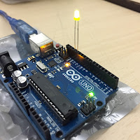
the connection making on bread board we connected our first output device- LED
on Arduino board’s digital output pin 13, On the micro controller pin 13 acted as positive terminal and GND-
Ground act as zero or negative terminal.
(blinking aurdino led) it was blinking because the the reset code used was
blink.
The Coding for this command was -
// the setup function runs once when you press reset or power the board
void setup() {
// initialize digital pin LED_BUILTIN as an output.
pinMode(LED_BUILTIN, OUTPUT);
}
// the loop function runs over and over again forever
void loop() {
digitalWrite(LED_BUILTIN, HIGH); // turn the LED on (HIGH is the voltage level)
delay(1000); // wait for a second
digitalWrite(LED_BUILTIN, LOW); // turn the LED off by making the voltage LOW
delay(1000); // wait for a second
}
*Here the words – HIGH & LOW in digitalwrite means ON & OFF for any Digital output and delay is time in milli seconds and can be altered accordingly.
The same command can be repeated by applying numerous LEDs on different pins and assigning them different codes. :)
LED with Buzzer : It did not need any other code as the same codes used for two output for 2 LEDs can be used as the number of outputs did not change.
Changing the LED with variable resistor , here TRIM, it is a small construction of potentiometer.
IR Sensor - We used IR sensor to detect IR emitting objects, maybe humans, and other objects.It can also detect any obstacle towards it is pointed. And it can be understood as digital output.
The code used :
the
setup routine runs once when you press reset:
void
setup()
{
// initialize serial communication at 9600 bits per second:
Serial.begin(9600);
// make the pushbutton's pin an input:
pinMode(2, INPUT);
pinMode(13,OUTPUT);
}
//
the loop routine runs over and over again forever:
void
loop()
{
// read the input pin:
int ugPdl = digitalRead(3);
if (ugPdl ==0)
{
Serial.println("Obstacle detected , Be
careful");
digitalWrite(13,HIGH);
delay(1000);
digitalWrite(13, LOW);
}
else
{
Serial.println("obstacle not detected ,
continue");
digitalWrite(13,LOW);
}
// print out the state of the button:
Serial.println(ugPdl);
delay(1000); // delay in between reads for stability
}
LDR
Resistor - As we knew that it can be
used to detect changes in light and intensity of light. So to know the
change by the output device or can get
the value on device used as output screen.(Here Laptop)
Code :
//
the setup routine runs once when you press reset:
void setup() {
// initialize serial communication at 9600 bits per second:
Serial.begin(19200);
// make the LDR sensor's pin an input:
pinMode(A0, INPUT);
pinMode(2, OUTPUT); //here output refers to that of attached LED's for visual data
}
void setup() {
// initialize serial communication at 9600 bits per second:
Serial.begin(19200);
// make the LDR sensor's pin an input:
pinMode(A0, INPUT);
pinMode(2, OUTPUT); //here output refers to that of attached LED's for visual data
}
//
the loop routine runs over and over again forever:
void loop() {
// read the input pin:
int a = analogRead(A0);
if (a>=x)
{
Serial.println("abcdef");
digitalWrite(2, HIGH);
}
else
{
Serial.println ("ghijkl");
digitalWrite(2, LOW);
delay (1000);
}
void loop() {
// read the input pin:
int a = analogRead(A0);
if (a>=x)
{
Serial.println("abcdef");
digitalWrite(2, HIGH);
}
else
{
Serial.println ("ghijkl");
digitalWrite(2, LOW);
delay (1000);
}
Servo
Meter – Servo meter was used next on arduino UNO .The aim for using it with
Arduino was using it at the specific angles as well as controlling the time
period for repetition.
the code for it:
#include
<Servo.h>
Servo
myservo; // create servo object
to control a servo
//
twelve servo objects can be created on most boards
int pos
= 0; // variable to store the servo position
void
setup()
{
myservo.attach(9); // attaches the
servo on pin 9 to the servo object
}
void
loop() {
for (pos = 0; pos <= 180; pos += 1)
{
//
goes from 0 degrees to 180 degrees
// in steps of 1 degree
myservo.write(pos);
// tell servo to go to position
in variable 'pos'
delay(15);
// waits 15ms for the servo to reach the position
}
for (pos = 180; pos
>= 0; pos -= 1)
{
//
goes from 180 degrees to 0 degrees
myservo.write(pos);
// tell servo to go to position
in variable 'pos'
delay(15);
// waits 15ms for the servo to reach the position
}
}
{ERROR OCCURED WHILE UPLOADING VIDEO CONTENT}
DC
Motor is any class of rotary electrical machines that converts direct current
electrical energy into mechanical energy .
for
this we will need a transmitter and wires , solder , solder stick and a
screwdriver .
first
solder two wires at both the terminals of the DC motor
then
unscrew the screws at left or right forward and backward
thereafter
connect the two wires on the DC motor and tighten screws.
connect
VCC , GND and pins
The Code is:
Aim:
To run the motor with the help of arduino board and transmitter
code:
const int
leftForward = 5;
const int
leftBackward = 6;
const int
rightForward = 4;
const int
rightBackward = 2;
void
setup()
{
pinMode(leftForward , OUTPUT);
pinMode(leftBackward , OUTPUT);
pinMode(rightForward , OUTPUT);
pinMode(rightBackward , OUTPUT);
}
void
loop()
{
analogWrite(leftForward , 150);
analogWrite(leftBackward , 0);
delay(2000);
analogWrite(leftForward , 0);
analogWrite(leftBackward , 150);
delay(2000);
analogWrite(rightForward , 150);
analogWrite(rightBackward , 0);
delay(2000);
}


Comments
Post a Comment